Building a Coilgun: Round 4
At this point in the adventure, I am working at Hacksmith Entertainment, and have been instructed to build the largest coilgun we are legally permitted to construct.
How hard could it possibly be?
(And so began the legacy of Boaty McGunface. But we'll get back to that later.)
It so happens that I have to write an engineering report for this work term. It goes into formalized details about the final design, and a larger focus on the mechanical side of the picture.
The full report is available here.
The video of the project was released a few days after my work term ended. You can watch it on YouTube
From the start, we decided, for reasons that I hope are obvious, that our coilgun would have to be built so that it doesn't count as a firearm under the Canadian Firearms Act. This entails two key details:
- Less than 152.4 m/s of muzzle velocity or less than 5.7 J of muzzle energy.
- Must not resemble with near likeness an existing make and modle of firearm.
The good news is that 152.4 m/s is tremendously fast, and the nature of a coilgun is that it doesn't tend to fit inside of the skin of any existing make and model of firearm. Plus, bolting LiPOs to the shell of an airsoft M4 just doesn't sound worth the effort, when we could make something that looks so much cooler.
Furthermore, if the device is found to outperform the legal maximum velocity, we can easily hacksaw off coil stages until the system is legal to operate, so long as the batteries are disconnected first.
Ian, James, and I exchanged opinions on design specifications, and quickly reached several conclusions:
- Projectiles will be, roughly, the size of a Nerf dart (12.7mm dia. and 72mm long), so that we can call it a .50 caliber coilgun.
- Projectiles will be composed of mild steel, turned on a CNC lathe.
- A Nerf magazine will be used to feed the device.
- Muzzle velocity should not be in excess of 500 feet per second.
- Automatic fire will be available with a cyclic rate exceeding 2 rounds per second.
Which seemed quite nice on the face of things.
This did not, however, permit for any design decisions to be made. Balancing battery voltage, coil current, coil size, transistor price, battery safe operating limits, and stage count remained completely unchanged by those specifications. So we drew some lines in the sand:
- Power will be supplied by four 6s LiPo packs in series, delivering ~100V at full charge.
- The current draw will not exceed 400A for any meaningful length of time.
68101210 accelerator stages.- The coil current will be switched with D2PAK MOSFETs or IGBTs. My reasoning here was that we wanted board mount parts, and I don't trust the TO-247 package after my first experiments.
A delivery deadline was set (5 weeks!) and I was off to the races.
Ian offered to aid in the mechanical design aspect, especially where the repeating action was concerned. We settled on a linear stroke solenoid for moving the projectiles from the magazine into the lip of the first stage. With this design, open-vs-closed bolt would be a software decision, and would have no real impact on performance beyond lock time.
The first issue was to determine, given the barrel diameter, projectile length, and battery pack voltage, what size of coils to use.
This, in and of itself, was a tremendous balancing act. Curiously, though, there are only two variables: Coil OD, and wire gauge.
I wrote up a python program to calculate the expected coil field strength and current for arbitrary geometries, and used a slightly modified version to fill out a table of options for various wire thicknesses. The overwhelming conclusion was that, assuming an ideal voltage source and switch, a single turn of infinitely thick wire would win every time. We have neither an ideal switch nor an ideal source, so a more nuanced approach was needed.
The MOSFET's that we chose have a safe operating area that, reasonably, permits far higher currents to travel for a short periond of time (396A for 100µs) versus a long period of time (190A for 10ms). Earlier stages of the accelerator will have longer periods of activation than later stages, for the projectile will be (hopefully!) moving faster upon reaching them, and so spending less time within the area of affect (This raises some head-scratching conclusions about the physics of the projectile, but I'll talk about that later). So, the first stage would need to have more turns of copper to reduce the current to be within the safe operating curve of the MOSFET, while later stages would have fewer windings, allowing for a higher current to pass, but only for a brief period of time due to the transistor melting.
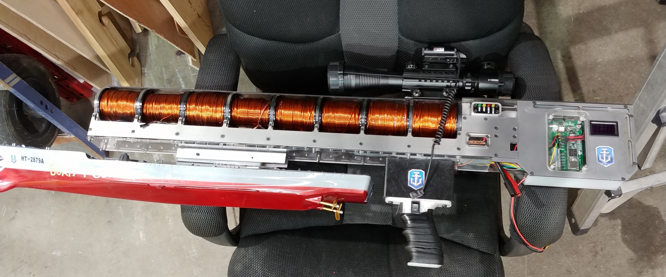
The numbers pointed towards using 14AWG enammled magnet wire to assemble the coils. The first stage would have an outer diameter of 65mm. The final stage would have an OD of 45mm, getting all of our currents to correspond to timings that we could expect the switches to survive.
As I was getting the design into one piece, we had the videography meeting, where James decided that it would be completely great to mount the coilgun on a model warship due to the sponsorship we had received. He quickly found an appropriate model, and several design parameters changed:
681012108 accelerator stages.- No repeating action.
Which lead to a bit of grumbling on my part, since I really wanted to build an automatic coilgun and make it as powerful as possible.
Ian was equally dissapointed by this plan, but it was soon decided that we would revisit the coilgun to build a bigger, badder, not-bolted-to-a-boat version with all 12 stages, that could actually be shoulder fired on full automatic.
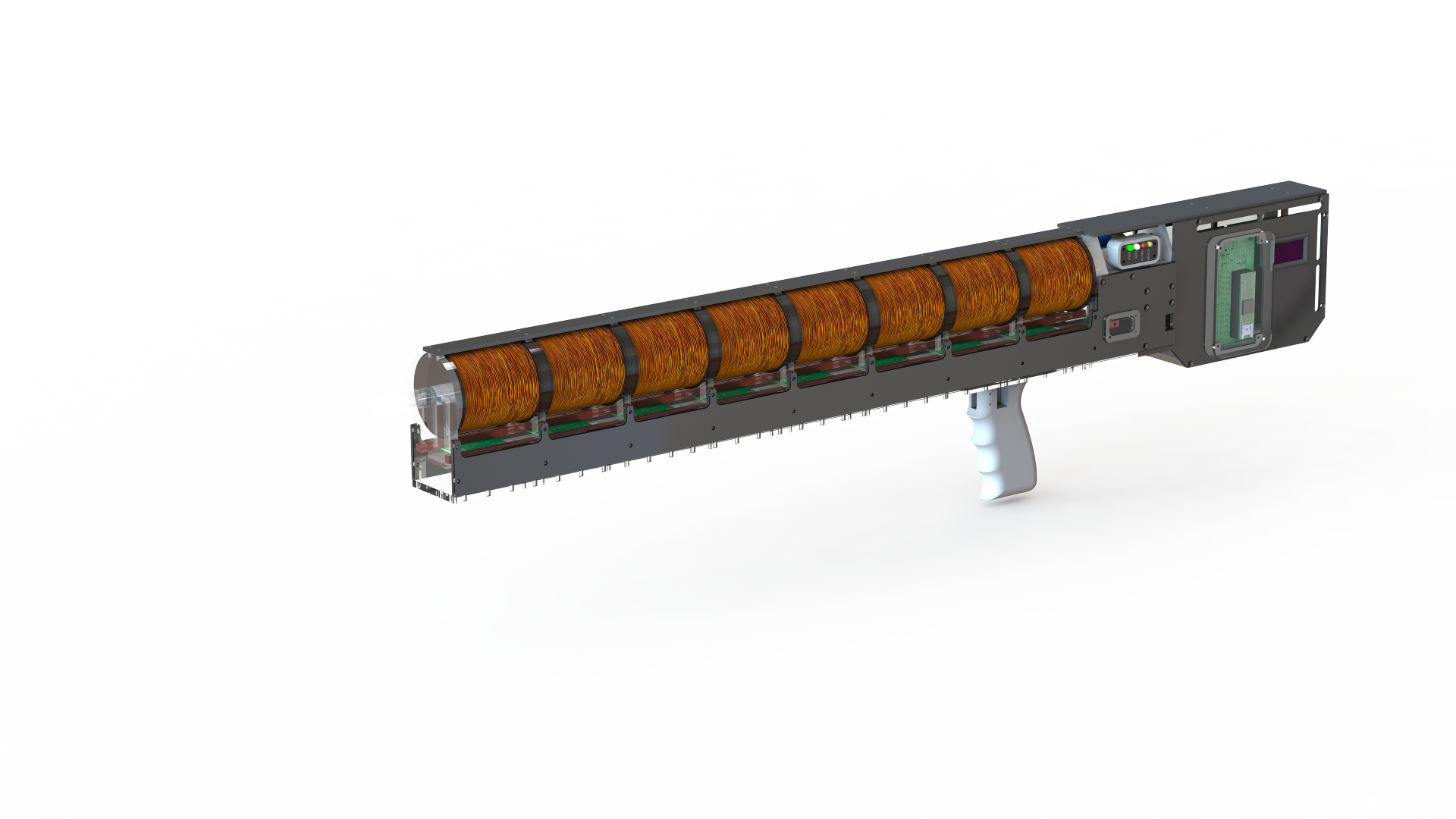
It took some effort, but at the end of the month,this is what the CAD looked like. I wound up soloing the CAD.
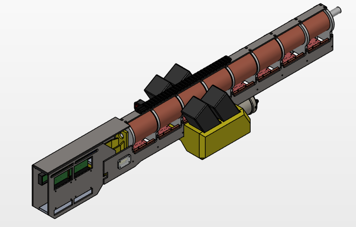
And, for fun, this is what it looked like before we made the decision to abandon free-fire and magazine feed. Note the giant relay under the barrel so that we would not need to remove the batteries.
Power
The power electronics side of the matter doesn't change at all between an eight-stage model and twelve-stage model. The timing should even be the same for the first eight accelerator stages. Which means that adding four more stages will be no tremendous effort.
Each stage consists of two electrically isolated halves: the low-voltage section and the high-voltage sections.
The HV section consist of a the MOSFET (Q2), the MOSFET-side of the gate driver (U18), a current sense resistor (R5), and the flyback circuit (D2, R1).
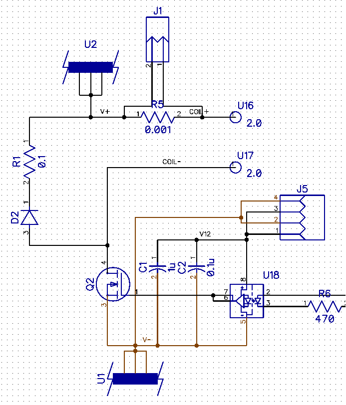
And yes, I may have failed to clean up the refdes numbers on this schematic.
U1 and U2 are the connections for the high-current, high-voltage power supply. J5 is the connection to the 15V supply.
Those U1 and U2 connections are special. Really, what connection can you trust to take a whole bunch of high-current pulses on a PCB, while still permitting easy removal of the board? That's right: a busbar!
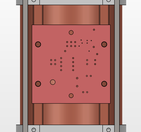

No, seriously, that's the plan: Bolt the PCB's exposed pad to a busbar. It worked very well.
Performance
How do we predict the performance of the system?
Frankly, no idea.
That said, there are a few things I can work with.
Whatver the exact equation for force on the projectile inside of a coil is, it does not depend on time, but it certainly (and, demonstrably,) depends on center-to-center distance between the coil and projecile. It's also, probably, proportional to the field strength, but I really don't know for sure.
If the force is directly controlled by the distance, then we can calculate the work done by the coil on the projectile. Work is the dot-product of displacement and force.
(Effectively) all of this work results in acceleration of the projectile.
This means that all of the stages should do the same amount of work.
That should mean that our projectile energy is proportional to the stage count, if all the stages had equally powerful magnetic fields. They don't (more on that later), but let's say they do.
Since kinetic energy, E=0.5*m*v^2, we should be getting, roughly, the square root of our stage count proportional to the projectile velocity.
Yes, those are diminishing returns in terms of velocity. But in terms of kinetic energy? That's spectacular!
This means that, if we can get 45 ft/s with a single stage and a 55g projectile (which, with an impractical coil geometry, we did) we should be able to get (2*sqrt(8 * (0.5 * 55g * (45ft/s)^2) / 55g)) = 180ft/s = 55 m/s = 197 km/hr out of an eight stage launcher, and 241 km/hr out of a 12 stage launcher. Which is, while still far shy of the legal limit, appreciable.
There are some weird takeaways here that make me question my reasoning:
- Later stages are quicker. They are enabled for less time, at (stick with the theory) the same power level. But in that time, they impart the same energy. So does that mean that later stages are more efficient? That can't be right!
- The field strength on later stages is way higher than in the first stage, so, assuming my understanding is correct, not only is our efficiency increasing, but so is our imparted energy per stage.
- This increase in efficiency between stages is huge. Our first stage (55 grams moving 45ft/s) is outputting 5.2J with an (estimated) 140A, 125V coil, activated for 10.5ms. That's a stage efficiency of 2.8%, which is not too great. But our second stage will be much quicker than that (maximum of 2.5ms), which would mean 11.9% efficiency, which would be really good for a coilgun. Unbelieveably good, in fact. And that has me worried. When we actually have performance numbers, we'll see how that works out!
- There must be some variable I'm failing to consider, because according to this model, the stage would break 100% efficiency at a 300µs firing window. That said, the inductive nature of the coil would make it impossible to have a full current pulse at that length. I don't understand electromagnetism well enough to figure this out.
What this does suggest is that bumping into the legal limit with a 125V system and a 190A DC current limit is not practical. We can, hopefully, beat linear energy/stage, though, so exceeding the projected 180 ft/s value should be possible.
Controlling the beast
On the low voltage side of the stage PCB, we have a feedback system that amplifies the signal from a photodiode and passes it back down the wiring harness to the controller. The photodiode and its accomponying LED are sat diametrically opposite eachother across the barrel, inside of the plastic supports that go between each pair of stages.
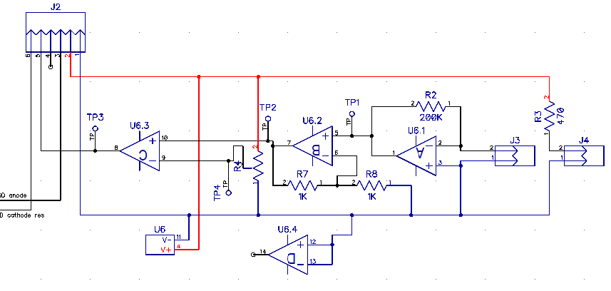
This provides the computer with a digital signal saying whether that spot in the barrel is empty or not. Sadly, that spot is several millimeteres behind the spot where we would want the front of the projectile to be when we turn on the next coil, and several millimitres ahead of where we would want the rear of the projectile to be when we turn off the next coil. The spacing between centres of coils is about 12mm longer than the projectile (and, subsequently, coil) length.
There are only two things we can do with the coils in software: Turn them on, and turn them off. The trick is figuring out when to do those two things.
Problem 1: Turning off.
Ideally, the field strength of the coil would drop to zero the instant the projectile's center of mass passes through the center of the coil. Sadly, electromagnets don't work that way. They are inductive loads, so the current through them cannot change instantly, and since the magnetic field strength is proportional to the current, we can't change that instantly either. There has to be an exponential decay of the field strength.[2]
For obvious reasons, we don't want the coil to have a net pull on the projectile that will propel the projectile backwards, towards the operator[citation needed?]. Therefore, the coil current should be decaying when we get to the center.
The coil produces the strongest forces when the projectile is at it's center, though. So we would be wasting the most effective region of operation. What we want is for the decay to be happening when the projecile hits the centre, giving us more forward pull at the cost of a little bit of backwards pull. For this to be effective, we need the "backwards" impulse to not exceed the "forward" impulse that we gained from traipsing dangerously over this line. The changing inductance of the coil as the projectile moves stands to make this very difficult to predict.
So, in short, we need to turn off the transistor right before the projectile's center passes the center of the coil. We should, then, be switching off on the falling edge of the feedback signal. The question becomes: What's the time-constant for turn-off... in millimetres?
Problem 2: Turning on.
The coil's full-current activation time cannot place the MOSFET outside of its safe-operating-area. For this reason, there is a hard line before which we cannot turn on the coil transistor.
We want the coil to be at full strength before the front of the projectile reaches the rearmost edge of the coil. Since we can only turn on one coil at a time[1], we can't get the next coil "warmed up" while the previous coil is still on. Except, it turns out, we totally can, because the gradually increasing current never overlaps to get our combined current between two stages above 400A. The distance between the center of one coil and the front edge of the next is not nearly far enough to get the next one up to full current, so doubling up would be neccessary for good performance.
The following table gives, assuming constant per-stage energy, the projected stage entrance speed, and the maximum coil energization time for it to cover half the interstage length (d/2), for each stage.
This is assuming 19.4m/s for the first stage. This is with an optimistic assumption of 19.4 m/s from the first stage.
Data generated with:
1..8 | %{units "(70mm+12mm)/2/ (2*sqrt($_ * (0.5 *55g*(45ft/s)^2)/55g ))" us -t}Constant-energy data table given known projectile characteristics
| N | Vi [m/s] | Td/2 [µs] |
|---|---|---|
| 1 | 0 | 10,500 (Does it's own thing) |
| 2 | 19.4 | 2113 |
| 3 | 27.4 | 1495 |
| 4 | 33.6 | 1220 |
| 5 | 38.8 | 1057 |
| 6 | 43.4 | 945 |
| 7 | 47.5 | 863 |
| 8 | 51.3 | 799 |
If we look at Figure 8 on page 4 of the IRFS4115pbf datasheet[3] we find the Maximum Safe Operating Area. This tells us how much current we can run through the transistor without it failing on us.
This table suggests that we're not going anywhere near our coveted 100µs maximum current pulsing. We'll still be pushing a whole whackload of current (290A for 1ms). There's current being left on the table, but there's no sense chasing it.
Time constants
We can predict the time constant for the coils, since we can predict their resistance and their inductance. However, the confusion of having a variable core material makes that more difficult[4].
This was an excellent resource. But, with the coils finally built, all of the data went completely out the window. The predicted inductances were several times higher than we measured. And on top of that, the non-uniformity of the core (Some of it was steel, some of it was air, much of it was copper, some of it was polycarbonate.) made things difficult. Luckily, the measured inductances were lower, not higher, than the predicted values. But, still, the time constant of the coils were far above the expected coil time.
Coils
No plan has ever survived first contact with the machine shop.
Several compromises against ideal performance had to be made to be able to deliver this project in 5 weeks. First, assembling the coils straight onto the barrel was deemed impractical. By which I mean, with the tools we had, impossible.[5]
So we opted to make the coils self-epoxied and rigid, so that they could be slid down the barrel into position between the stage seperators. To this end, a steel mandrel for winding the stage coils was turned and plasma-cut, permitting us to have a surrogate barrel in a drill chuck, and wind the wire onto that instead.
We encountered problems with this plan.
The mandrel was cut slightly oversized. However, with winding several hundred metres of 14AWG wire onto it, the wire tended to spring back a little bit. Which is to say, we could not remove the coils in quite as pristine condition as we had hoped. For this reason, we wound up scrapping several kilos of copper wire. Contemplation of the correct route forward, though, gave an opportunity to test out a single stage and our tuning process. With a chunk of random 1/2" steel rod we had lying around the shop, we could get a fairly significant response with 125V and a stage controller. We were acheived around 45 ft/s with this single stage, suggesting that we could get well over 125ft/s with the final product (V=sqrt(n*V^2) for n=8, v=45ft/s).
In short, it became difficult to force the coils onto the 5/8" OD polycarbonate pipe that served as the inner barrel of the gun. We wound up, in this most informative first case, removing it from the twelve feet of polycarbonate stock with a hacksaw. That length of pipe remained in that coil forevermore. An design change was made: The coils would be wrapped around oversized sections of polycarbonate pipe that would then be slid, gently, elegantly, and smoothly, down the outside of the 5/8" OD of the inner barrel.
These came off of the steel mandrel just fine. And the lengths of 5/8" ID pipe that we used slid smoothly down the barrel.
Or, at least, they did. Until we wrapped a pound of wire around them under a hundred pounds of tension. The tube's ID decreased by just enough to make things difficult. We needed to use a variable-angle swing-press[6] to acheive a fit. This one we did manage to remove from the barrel, but it took additional brute force, this time in the opposite direction.
Scratching our heads, we tracked down the large-diameter drill index, only to find that we did not own a 5/8" drill bit, nor a 11/16" drill bit. What we did have was some 5/8" OD steel pipe. And a file...
...and a power drill....
So, feeling the distant cries of a thousand anguished toolmakers, I cut two flutes into the outside of the tube, cut in some rake, relief, and clearance, and affixed a 1/2" steel rod into the center of the tube. I then clamped the coil assembly in a vice, grabbed one of the shop hand drills, and gave it a go.
This, contrary to reasonable expectations, worked great. The improvised reamer got the ID of the coil sleeves down to the perfect size for a nice, tight fit along the inner barrel. And with that, we could proceed to improve the design. Acrylic end plates were added to the coil assemblies to keep them nice and intact, and to give a clearly defined starting place for where the wire goes. These plates were laser cut and then pressed and superglued to the ends of the cut and sanded down tube sections.
Armed with my performance estimates, I handed Dave and Dalton a list of coil sizes, and went to finish the electrical assembly.
Electrical
Everything went according to plan. No, seriously. We did not have to scrap any boards, or any parts. Except, of course, for the inevitable few 0603 resistors that teleported into a parallel universe when tweezers were misused.
Let's call it acceptable losses.
With some help from the trusty Tormach CNC mill, I drilled all of the holes we need for the stages in the busbars, and test fit all of the PCBs. With those bolted down, I assembled the rather intricate ribbon cables to connect all of the stage controllers to the control connector on the main board. The thirty-wire ribbon had to be split into pairs of wires to get four shared and two specific wires to each stage controller board. This took maybe half an hour. The 30-pin end of the wire was left intact until final install time, because that was not a length I wanted to guess at.
At this point, four of the eight stage coils were complete, so we performed some initial assembly. Which, for some reason, we recorded as final assembly. Dalton and I tuned it up to the best of our abilities with the four stages running at 100V. The next day, Dave completed the remaining four stages, so we installed those and got to tuning.
It took roughly a day to completely tune the coilgun for Single Stage Tuning, wherein only one stage is live at a time. We acheived, after some significant effort, a cool 80 ft/s.
| Stage | Tvmax | Vmax | Vmetric [m/s] | Videal [m/s] | U [J] | U ideal [j] |
|---|---|---|---|---|---|---|
| 1 | 11750 | 33.9 | 10.33272 | 10.33272 | 3.256335629 | 3.256335629 |
| 2 | 6250 | 45.7 | 13.92936 | 14.61267276 | 5.917825635 | 6.512671259 |
| 3 | 4950 | 53.2 | 16.21536 | 17.89679602 | 8.019605948 | 9.769006888 |
| 4 | 4300 | 59.4 | 18.10512 | 20.66544 | 9.997758792 | 13.02534252 |
| 5 | 3850 | 66.1 | 20.14728 | 23.10466431 | 12.38034319 | 16.28167815 |
| 6 | 4000 | 71.4 | 21.76272 | 25.30989166 | 14.44528744 | 19.53801378 |
| 7 | 3650 | 76.5 | 23.3172 | 27.33780749 | 16.58260038 | 22.7943494 |
| 8 | 3700 | 80.8 | 24.62784 | 29.22534552 | 18.49918034 | 26.05068503 |
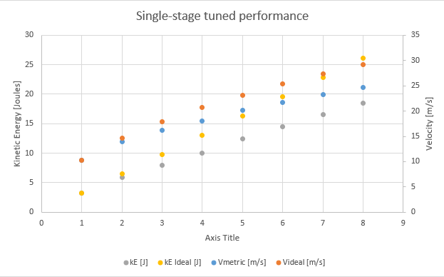
The grey and yellow scatters represent the realized and ideal kinetic energy of the projectile. This shows that we were falling very short of ideal performance.
So, one fine Good Friday, I thought, hey, what would happen if we pre-warmed the coils? As in, turn on two at a time? At all times in the firing sequence but the last millisecond, have two stages active? So I drove to the shop, set up with some music, and proceeded to, of course, blow up the coilgun three or four times.
It was one of those days.
Pictured above is the second explosion of the day. The fuse on the main power line gave, and it gave quite a show in the process.
The reason for the failure was slightly over-aggressive tuning of stages 7 & 8. The MOSFETs in one or the other failed closed, letting 320A through the system (not actually a dangerous state for the batteries!) continuously. As planned, the fuse took the worst of it, and promptly killed itself within about half a second. By some mechanism, this killed the other of those two, and stage 6. This was a painful one to fix.
When things go wrong.
This was the first shot with this tuning. The eighth stage was set active for 3100µs. The final tuning was 3000µs.
Once the smoke cleared and I had replaced the destroyed PCBs, I finalized the tuning, and we were all set to go for the Monday. At least, it would've been set to go if I hadn't broken the thing again at 9:00 at night.
Monday morning, I repaired what I had previously fixed (The wire for the safety got loose, entirely disabling the gun), and we were off to the races with launching chunks of steel across the shop floor.
| Stage | Tvmax | Vmax | V | V ideal | U | U ideal |
|---|---|---|---|---|---|---|
| 1 | 11400 | 33.9 | 10.33272 | 10.33272 | 3.256335629 | 3.256335629 |
| 2 | 6500 | 49.8 | 15.17904 | 14.61267276 | 7.027299287 | 6.512671259 |
| 3 | 4000 | 60.1 | 18.31848 | 17.89679602 | 10.23478464 | 9.769006888 |
| 4 | 4000 | 67.7 | 20.63496 | 20.66544 | 12.98694801 | 13.02534252 |
| 5 | 3750 | 76.3 | 23.25624 | 23.10466431 | 16.49600732 | 16.28167815 |
| 6 | 3000 | 82.8 | 25.23744 | 25.30989166 | 19.42631552 | 19.53801378 |
| 7 | 2000 | 88.1 | 26.85288 | 27.33780749 | 21.99285351 | 22.7943494 |
| 8 | 2800 | 93.8 | 28.59024 | 29.22534552 | 24.93075561 | 26.05068503 |
Later that week, when the smoke and debris had cleared from spending two days putting large steel slugs into various targets, I sat down and plotted our velocity data.
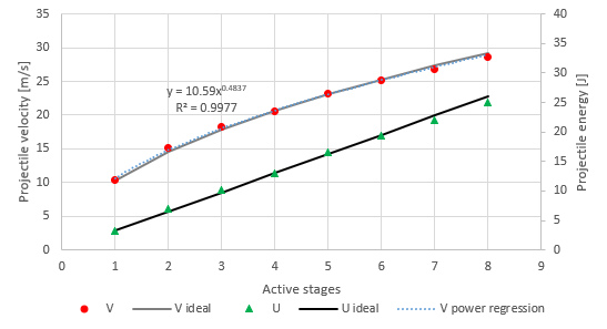
This is pretty compelling evidence that all of the stages, except the two at the end that I had to intentionally turn a bit down, were running at ideal performance. The incremental energy from each stage is almost perfectly constant.
Just how much power were we using there?
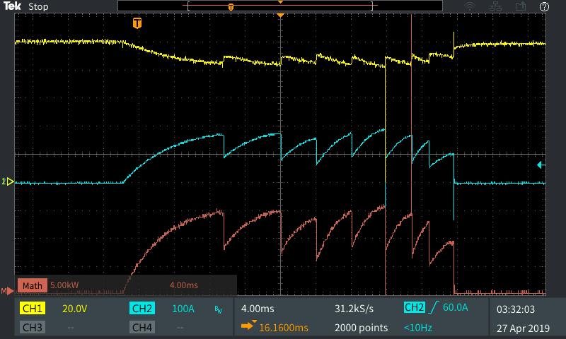
A lot. The input current peaked at around 195A, which is dramatically lower than expected, since that's for two stages! The consumed power, excluding losses in the power lines, hit 16kW while stage 5 and 6 were active.
Yes, I did expect that number to be higher.
So why did we not get the 200A/stage that we wanted?
LR time constants are a pain in the ass. More precise timing is necessary to get more power into this thing. And bigger transistors are needed to get more power through through all this.
"We missed the boat!"
...was a thing we would have said to James had we not remembered that we promised to afix it midway through preparing for the shot Monday morning.
So, acting quickly, and using only a scrap pile, a permanent marker, some back of the envelope calculations, and a CNC laser cutter and mill, Dalton and I whipped up a set of parts that we could bolt to the bottom plate of the coilgun barrel assembly to mount, firmly and removeably, the boat. A few details got misplaced during construction, leading to the screws being used as pins (But don't tell YouTube!). In my defense, I thought those holes were tapped. And aligned. In the cardboard-aided-design, they had been.
With these final changes made, we ate lunch, hung a welding blanket across the garage door, set up the tripods, and got shooting.
With the cameras finally rolling, James took a gold Sharpie out of the toolbox, and christened the refitted vessel "Boaty McGunface".
How to do it better next time?
Well, I am glad you asked!
First, here's the actionable changes:
- More MOSFET. Switch to a TO-247 package, or several D2PAKs, or (Going all in) miniBLOC.
- MiniBLOC would have the fun benefit of permitting rapid replacement, since the transistor would have to be bolted to the PCB.
- Would also require a bigger flyback diode.
- You can just... keep spending money on transistors, and keep receiving bigger ones.
- 3D print the coil frames as modular units. This gives a lot of benefits:
- Tighter coils: Less inductance, more magnetic field, lower resistance. These are all good things.
- Simpler assembly: No screwing around with improvised drill bits to get an inner barrel to fit properly.
- Better fit and alignmnet guarantees for photogates: Functional control feedback.
- Magazine feed, which would permit...
- Automatic repeating. There's no reason we can't, both legally and technically, so long as we keep under 152.4 m/s.
- Smaller projectiles, although it's really a matter of taste.
- 25J in a 5g projectile is 100 m/s.
- While there is a certain spectacle to throwing giant steel slugs, having a projectile go way faster, even if its smaller, would be entertaining in a seperate way.
- Using, say, a 6.00 mm projectile would allow use of a standard, store-bought, .22lr magazine, saving some actual engineering work.
- More than eight stages.
- Use the smallest possible batteries, and mount them on the chassis.
- Design and tune the system use every last milliwatt of power avaialble in those batteries.
- Switch to a 30S LiPo battery pack, for 125V.
- I want to drive a lot of power from this thing. Let's say, maybe, 500A.
- We're only concerned with burst current discharge, usually rated against 10 or 3 seconds.
- If we have a large enough magazine that we can sustain fire for longer than the burst current rating, uh, well, then the focus should be on increasing the fire rate. Or,
- Batteries that big are out of my price range. This will likely require a return to the Hacksmith shop.
- Get a more appropriate fuse. As exciting as purple flashes are, I prefer to avoid unexpected explosions.
And the slightly less actionable ideas:
- Make it lighter.
- Find a way to stabilise the projectile.
- Knowing what I know now, create better performance estimates, allowing for better design optimization.
- Should be able to beat constant energy per stage with an appropriate electrical design.
Footnotes:
[1]: We gave ourselves a hard limit of 400A from the batteries. After the first two or three stages, I>200A, so that's not going to work, and I'd hate to have to find a safe way to program that.
[2]: You can probably do better than exponential, but I don't know exactly how. Putting a resistor in the flyback circuit will make the rolloff more dramatic, but they kept exploding.
[4]: Or maybe it's just as easy as calculating it with either a mild steel core or an air core and using those as the inductances for either end of the current pulse, granting us two time constants?
[5]: And by "impossible", I mean "impossible to do safely without significant time and material investment in setup and tooling so that nobody loses an eye in the process".
[6]: Hacksmith shop parlance for "hammer".
[7]: Constant energy assumes that current as a function of relative projectile distance I(x) is the exact same for each stage. This assumption breaks down for several reasons, but if we can have the coil at "steady state" by the time the projectile enters the field of influence (Say, the last 25% of travel of the previous stage) we can acheive ideal energy input at each stage. And since the coil current should increase at every stage, we should be able to beat constant energy. This just leaves the trouble of flyback suppression. Every microsecond where current is flowing after the projectile passes the midway point costs muzzle energy. Getting the length of that time down is doable, but requires raising the voltage rating on the transistor (Because Vds = Vss-Vdd + I*Rflyback), and using physically large pulse-rated resistors. For a sense of scale, the energy stored in each coil at full tilt is E=I^2*L/2=(5mH)*(100A)^2*0.5=25J in a low-current case. This, as shown in the video, will blow even the heartiest surface mount resistors into a fine powder if released in ten microseconds (25,000,000 W, in case you were wondering). So, really, really big resistors are needed. Things like the HSA50 series are larger than the projectile itself, but are rated for these conditions. How do you make that fit? No idea. Adding a capacitor could help too, but that would also be physically large.